
5-axis precision grinding to plus or minus 0.001mm on suitable features. When milling cannot hold the tolerance, surface finish, or flatness your drawing calls for, grinding is the finishing operation that gets you there.
Precision grinding is a finishing operation. It takes a part that has been machined or heat-treated and removes a small amount of material with an abrasive wheel to achieve tighter tolerance, better surface finish, or tighter geometric control than milling can deliver. At Shenghao we run 5-axis precision grinders alongside our CNC milling and turning centers, so grinding is integrated into the production flow rather than outsourced to a separate supplier.
We hold plus or minus 0.001mm on ground features where the drawing requires it, against a standard CNC milling and turning tolerance of plus or minus 0.003mm. Grinding is used on hardened materials, tolerance-critical mating surfaces, sealing faces, gauge blocks, and parts that need specific surface finish for function or appearance.
| Tightest tolerance | ±0.001mm on suitable features |
| Surface finish | Ra 0.2 to 0.8 micrometer typical |
| Material hardness | Up to 60+ HRC |
| Grinding types | Surface, cylindrical, centerless, 5-axis profile |
| Certifications | Certificate documentation available on request. |
| Typical lead time | 15-25 days |
And where the line between them sits.
CNC milling removes material with a rotating cutting tool that has defined cutting edges. Grinding removes material with an abrasive wheel that has thousands of tiny cutting edges embedded in a bond matrix. The individual chip size is much smaller, which means grinding can hold tighter tolerance, produce smoother surfaces, and cut materials that are too hard for milling tools.
The trade-off is speed. Grinding is slower per unit of material removed than milling. That is why it is used as a finishing operation: mill the part to near-net shape, heat-treat if needed, then grind the critical features to final dimension. You do not grind a whole part from solid stock.
In practice, most parts do not need grinding. Our CNC milling and turning hold plus or minus 0.003mm as a standard capability, which is enough for most features. Grinding is called out on the drawing when a specific feature needs more than that: a sealing face that needs flatness, a bearing journal that needs roundness, a gauge surface that needs dimensional stability.
| Milling | Grinding | |
| Tolerance | ±0.003mm | ±0.001mm |
| Surface finish | Ra 0.8-3.2 | Ra 0.2-0.8 |
| Material hardness | Up to ~35 HRC | 60+ HRC |
| Material removal | Fast | Slow (finishing) |
| Role | Rough + finish | Finish only |
Flattens and finishes the top surface of a part. The wheel moves across a stationary workpiece mounted on a magnetic chuck or fixture. Used for parallel faces, flat reference surfaces, and sealing faces. The go-to for any part that needs tight flatness or parallelism.
Grinds the outside diameter (OD) or inside diameter (ID) of a rotational part. The workpiece rotates between centers or in a chuck while the grinding wheel moves along its axis. Used for bearing journals, shaft diameters, bushing bores, and seal surfaces.
Grinds the OD of a cylindrical part without holding it between centers. The part is supported by a work rest blade and driven by a regulating wheel. Used for high-volume pins, shafts, and rollers where throughput matters and the part is simple enough for the setup.
Grinds complex contours and profiles in a single setup. The grinding wheel moves along multiple axes simultaneously, following a programmed path. Used for turbine blade profiles, gear tooth forms, cam profiles, and other geometries that cannot be ground with single-axis movement. Where gear teeth are first cut by gear hobbing and then hardened, the profile is finished on the grinder after heat treatment.
| Flat surface | Surface grinding |
| OD of shaft/journal | Cylindrical OD |
| ID of bore/bushing | Cylindrical ID |
| Pin or roller, high volume | Centerless |
| Complex profile/contour | 5-axis profile |
| Gear tooth form | 5-axis profile |
| Sealing face flatness | Surface grinding |
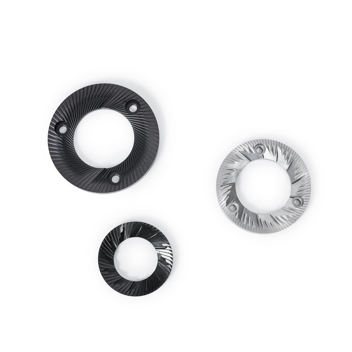
These flat burrs are ground after the tooth forms are cut, with the profiles held to the drawing and the faces ground for flatness. Where a drawing calls for a documented result, the ground features are inspected and reported with the order. The Mediso CT collimator shaft shows how that runs on a real part: laser-hardened to 52 ± 2 HRC, thread-ground, and shipped with a 3D dimensional report.
If your drawing does not call out grinding, we will quote the part as milled. If we think a feature needs grinding to meet the tolerance on your drawing, we will flag it in the DFM review.
Grinding is most commonly applied to hardened materials, where milling tools wear out too quickly or cannot achieve the required surface finish. Here are the materials we grind most often:
Through-hardened tool steels (D2, A2, O1), high-speed steel (M2), and carburized or through-hardened alloy steels (4140, 8620). These are the most common grinding materials because they are too hard for milling after heat treatment.
Hardened 17-4 PH and 420 stainless for medical and corrosion-resistant applications. Grinding achieves the surface finish and dimensional stability needed for sealing and mating surfaces in medical devices and instrumentation — see medical device manufacturing and instrumentation. Medical parts that need a documented quality route go through our ISO 13485 medical machining scope.
Tungsten carbide, technical ceramics (alumina, zirconia), and other hard materials that cannot be machined with conventional cutting tools. Grinding is the primary way to produce finished features on these materials.
| D2 tool steel | 60-62 HRC |
| A2 tool steel | 57-60 HRC |
| O1 tool steel | 58-62 HRC |
| M2 HSS | 62-66 HRC |
| 4140 hardened | 28-32 HRC |
| 17-4 PH | 38-44 HRC |
| 420 stainless | 50-54 HRC |
| Tungsten carbide | 70+ HRC |
We hold plus or minus 0.001mm on ground features where the drawing requires it. Our standard CNC milling and turning tolerance is plus or minus 0.003mm, so grinding is reserved for the features that genuinely need more than that. Grinding is used when a feature needs dimensional accuracy or surface finish that milling cannot achieve.
We grind hardened steel (through 60 HRC), tool steel (D2, A2, O1), high-speed steel (M2), carbide, hardened stainless steel (17-4 PH, 420), ceramic, and nickel alloys. Grinding is typically performed on hardened materials where milling would cause tool wear, heat distortion, or poor surface finish.
Surface grinding for flat surfaces and parallel faces, cylindrical grinding for OD and ID of rotational parts, centerless grinding for high-volume pin and shaft production, and 5-axis profile grinding for complex geometries and contours. The type depends on the part geometry and the feature being ground.
Choose grinding when your drawing calls for tighter tolerance than milling can hold (typically below 0.01mm), when the material is hardened and milling tool wear is excessive, when you need a specific surface finish (Ra below 0.4 micrometer), or when flatness, parallelism, or perpendicularity requirements exceed milling capability.
Yes. We can take parts that were rough-machined or heat-treated elsewhere and grind the finish features. Send the part or drawing with the as-machined condition and the final ground dimensions, and we will quote the grinding operation.
15 to 25 days for most grinding orders, depending on complexity, material hardness, and quantity. Grinding is slower per part than milling because it is a finishing operation with multiple passes. Exact lead time is confirmed with your quote.
Send your drawing revision, material grade, quantity and required delivery date. Highlight critical features, finishing requirements and the inspection documents you need. Achievable tolerances depend on geometry, material and the manufacturing route; we confirm them against your drawing.
Mediso CT collimator shaft — laser-hardened to 52 ± 2 HRC on the thread-grinding surface and thread-ground against a 0.005mm radial runout drawing requirement, shipped with a 3D dimensional report, material certificate and a go/no-go thread gauge check recorded in our own inspection documentation.
Read the Mediso case →Ivo titanium retainer and PA12 washer development — follow the drawing review, process planning and ongoing development work for Ivo USA.
Read the Ivo project account →Upload your CAD file with material, hardness, and tolerance callouts. Our engineering team reviews manufacturability and comes back with a quote. No automated pricing tool, no shared sales inbox.