
Simultaneous 5-axis and 3+2 positioning for parts with features on several faces, compound angles and contoured surfaces. Multi-sided geometry is cut in one fixturing, so features stay aligned to each other. Machined in Dongguan, China, to tolerances confirmed against your drawing.
5-axis CNC machining adds two rotary axes to the three linear axes of a standard milling machine. The extra rotation lets the tool reach five sides of a part in a single fixturing, instead of stopping, unclamping, repositioning, and re-zeroing between each face. That single-setup capability is what makes 5-axis the right choice for parts where features on different faces must align to each other within tight tolerances, or where the geometry is too complex for repeated 3-axis setups.
At Shenghao we run both simultaneous 5-axis (all five axes move during cutting, for contoured surfaces like impeller blades and turbine housings) and 3+2 positioning (the part is tilted to a fixed angle, then machined in three linear axes, for angled holes, pockets, and multi-sided prismatic parts). Most parts use 3+2; a smaller set of continuously curved parts need full simultaneous. We choose based on your drawing, not on what costs us more.
| Process | Simultaneous 5-axis & 3+2 positioning |
| Tightest tolerance | ±0.003mm (CNC) / ±0.001mm (grinding), when technically appropriate |
| Certifications | Certificate documentation available on request. |
| Typical lead time | 10–20 days |
| Materials | Aluminum, steel, stainless, titanium, brass, engineering plastics |
| Part envelope | Confirmed per RFQ, send your dimensions and we confirm fit |
The two extra axes, and why they matter more than the count.
A 3-axis mill moves the cutting tool in X, Y, and Z. It cuts one face at a time. To machine a second face, the operator stops the spindle, unclamps the part, rotates or re-fixtures it, re-zeros the coordinate system, and runs the next operation. Every repositioning is a chance for misalignment, and the cumulative error shows up in how well features on face A line up with features on face B.
A 5-axis machine adds two rotary axes, usually labelled A and B (rotation around X and Y) or B and C. On some machines the rotary axes live on the workbed, tilting the part; on others they are on the spindle head, tilting the tool. Either way, the machine can present the part to the tool at almost any angle without unclamping it.
3+2 positioning uses the two rotary axes to lock the part at a fixed angle, then cuts with three linear axes. It is fast, rigid, and handles the majority of real parts: angled holes, pockets on multiple faces, housings, brackets, manifolds.
Simultaneous 5-axis moves all five axes at once during cutting. The tool stays nearly perpendicular to the surface as it follows a curved path. This is what you need for impeller blades, turbine contours, organic surfaces, and anywhere the tool must tilt continuously to maintain contact. The same continuous tool orientation is what holds the contour on semiconductor chamber and gas-handling components. It is slower per minute of cutting but reaches geometry 3+2 cannot.
| X, Y, Z | Three linear axes (standard) |
| A | Rotation around X |
| B | Rotation around Y |
| C | Rotation around Z |
| 3+2 | Rotary axes fixed, then 3-axis cut |
| Simultaneous | All 5 axes move during cutting |
And when it is not. We will not oversell it.
Parts that typically benefit: machined housings and manifolds, brackets with angled faces, instrument bodies, and contoured flow components such as impellers.
Send your drawing and our engineers recommend the process that meets your tolerance at the lowest cost. If 3-axis does the job, we say so.
| Factor | 3-axis | 5-axis |
|---|---|---|
| Setups for a multi-sided part | Multiple, one per face | One, in a single fixturing |
| Feature-to-feature accuracy | Limited by repositioning error | Held in one setup, typically tighter |
| Tool length and rigidity | Longer tools to reach, more deflection | Tool can tilt, shorter and stiffer |
| Contoured surfaces | Not possible without repositioning | Simultaneous mode cuts them directly |
| Cost per part | Lower for simple geometry | Lower when it removes setups |
| Best for | Flat parts, single-face pockets, prototypes | Multi-sided, angled, contoured, tight-tolerance parts |
5-axis often costs less per finished part than 3-axis on complex geometry, because the setup time it removes is more expensive than the machine time it adds.
A broad range of metals and engineering plastics. Full list with finishing cross-reference on our Materials & Finishes page →
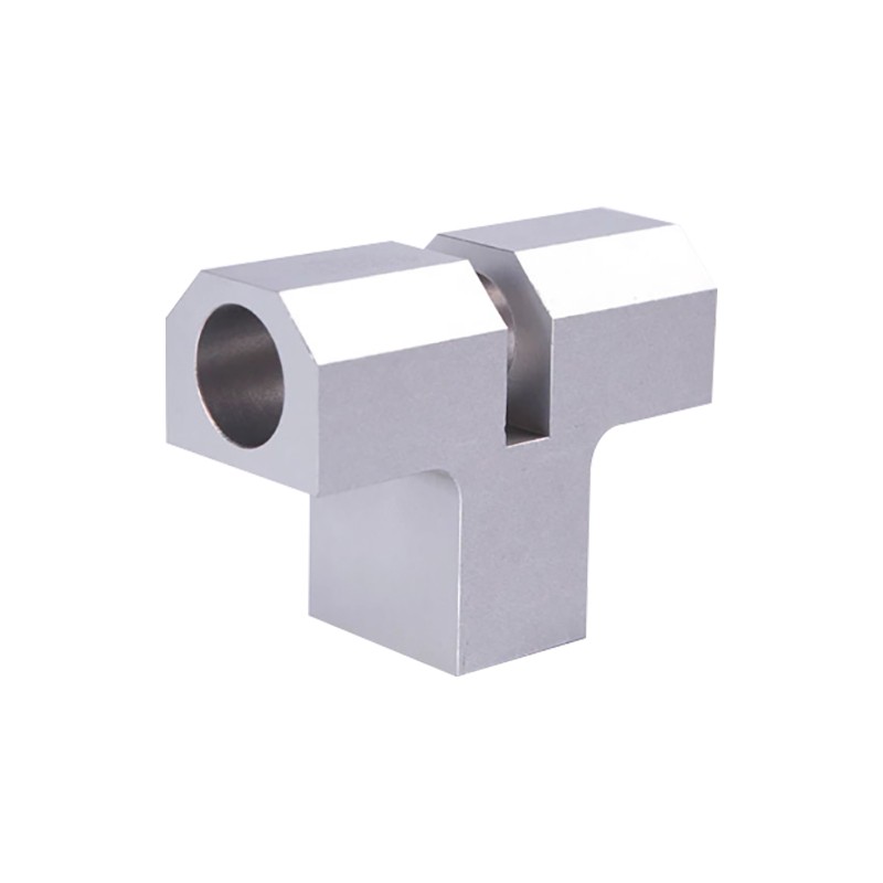
6061, 7075, 2024. Common for housings, brackets, aerospace structural parts.
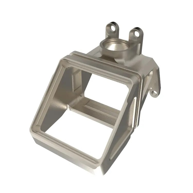
1018, 1045, 4140, 304, 316. Shafts, fittings, structural and medical components.
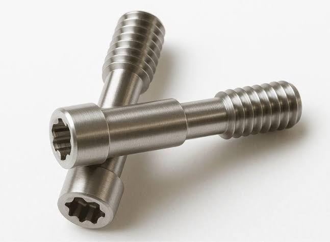
Grade 5 (Ti-6Al-4V). Aerospace, implant-adjacent medical components, high strength-to-weight parts.
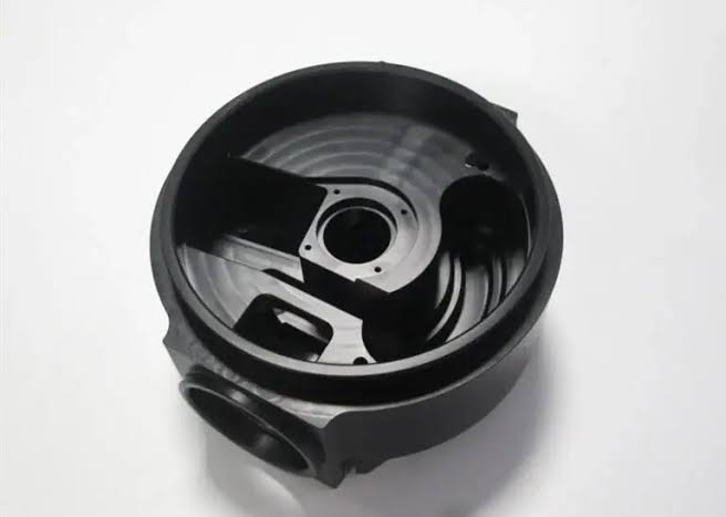
Delrin, Nylon, PEEK, PTFE, PC. Insulators, housings, low-friction components.
Material choice drives feeds, speeds, and lead time, all confirmed with your quote.
These are capability figures, not a default. What a part can actually hold depends on its geometry, feature size, material, setup and inspection requirements.
| Linear dimension | ±0.003mm (CNC) / ±0.001mm (grinding), when technically appropriate |
| Feature-to-feature (single setup) | Typically tighter than multi-setup 3-axis, confirmed per drawing |
| Hole diameter (not reamed) | Confirmed during engineering review |
| Shaft diameter | Confirmed during engineering review |
Tolerances vary by geometry, feature size, material, setup and inspection requirements. Critical dimensions are confirmed during engineering review, against your drawing. For how tolerances accumulate across features and operations, see how tolerance stack-up works in CNC machining.
Complex parts usually fail at the handoff between features, not inside them. Inspection is planned around that.
Because 5-axis work machines several faces in one fixturing, those features stay in a single coordinate system from the first cut. That carries into inspection: dimensions that would otherwise be checked across several re-datumed setups can be verified against one datum, which is where most multi-setup discrepancies originate.
Critical dimensions, datums and GD&T callouts should be identified at the RFQ stage rather than after the parts are cut. If a drawing is ambiguous about which feature controls the datum, we raise it before quoting, not after inspection.
Inspection runs through four stages on every order: incoming material check — material certification verified against your spec before it reaches the machine; in-process inspection — operators check dimensions against your print at set intervals through the run; final inspection — first article and final inspection against your drawing before parts ship; and reporting — dimensional reports and traceability documentation ship with the parts. Details on our Quality & Certifications page.
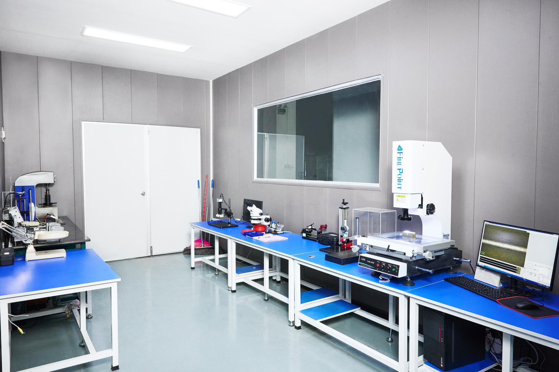
| Incoming | Material certification checked against your spec |
| In-process | Dimensional checks at set intervals through the run |
| Final | First article and final inspection against your drawing |
| Reporting | Dimensional reports and traceability documentation |
Simultaneous 5-axis moves all five axes at once during cutting, which is required for smoothly curved geometry like impeller blades and turbine contours. 3+2 positioning fixes the part at an angle using two rotary axes, then machines with three linear axes, which is faster and more rigid for angled holes, pockets, and multi-sided features that are not continuously curved. Most parts use 3+2; a smaller set of contoured parts need simultaneous.
Choose 5-axis when your part has features on multiple sides that must be aligned to each other within tight tolerances, deep pockets that need a shorter tool to reach, undercuts, or contoured surfaces like blades and impellers. Choose 3-axis for simpler flat geometry, pockets on one face, or lower-cost prototypes. We review your drawing and recommend the most cost-effective approach, not the most expensive one.
We hold ±0.003mm on 5-axis work when the geometry, material and features allow, and ±0.001mm on ground features. Because 5-axis machines complex geometry in one setup, feature-to-feature accuracy is typically better than repositioning across multiple 3-axis setups. Exact tolerances are confirmed against your drawing with every quote.
Aluminum, steel, stainless steel, titanium, brass, copper, and engineering plastics including Delrin, Nylon, PEEK, and PTFE. Material choice affects feeds, speeds, and lead time, all confirmed with your quote.
Typically 10–20 days for 5-axis CNC orders, depending on complexity, material, finish and inspection requirements. 5-axis can reduce total lead time versus 3-axis by reducing setups. Exact timing is confirmed with your quote.
A 3D model or 2D drawing (STEP, IGES, SLDPRT, DXF or PDF), the material, the quantity, and any critical tolerances or finishes marked on the print. If you have a target date, include it. We review the drawing before quoting and flag anything that affects cost or lead time.
Yes. Ask for our NDA before you send anything and we will get it signed first. We do not send one unprompted, so ask if you need it in place.
Upload your CAD file (STEP, IGES, SLDPRT or DXF), material, quantity, and deadline. Our engineering team reviews manufacturability and comes back with a quote. No automated pricing tool, no shared sales inbox.