
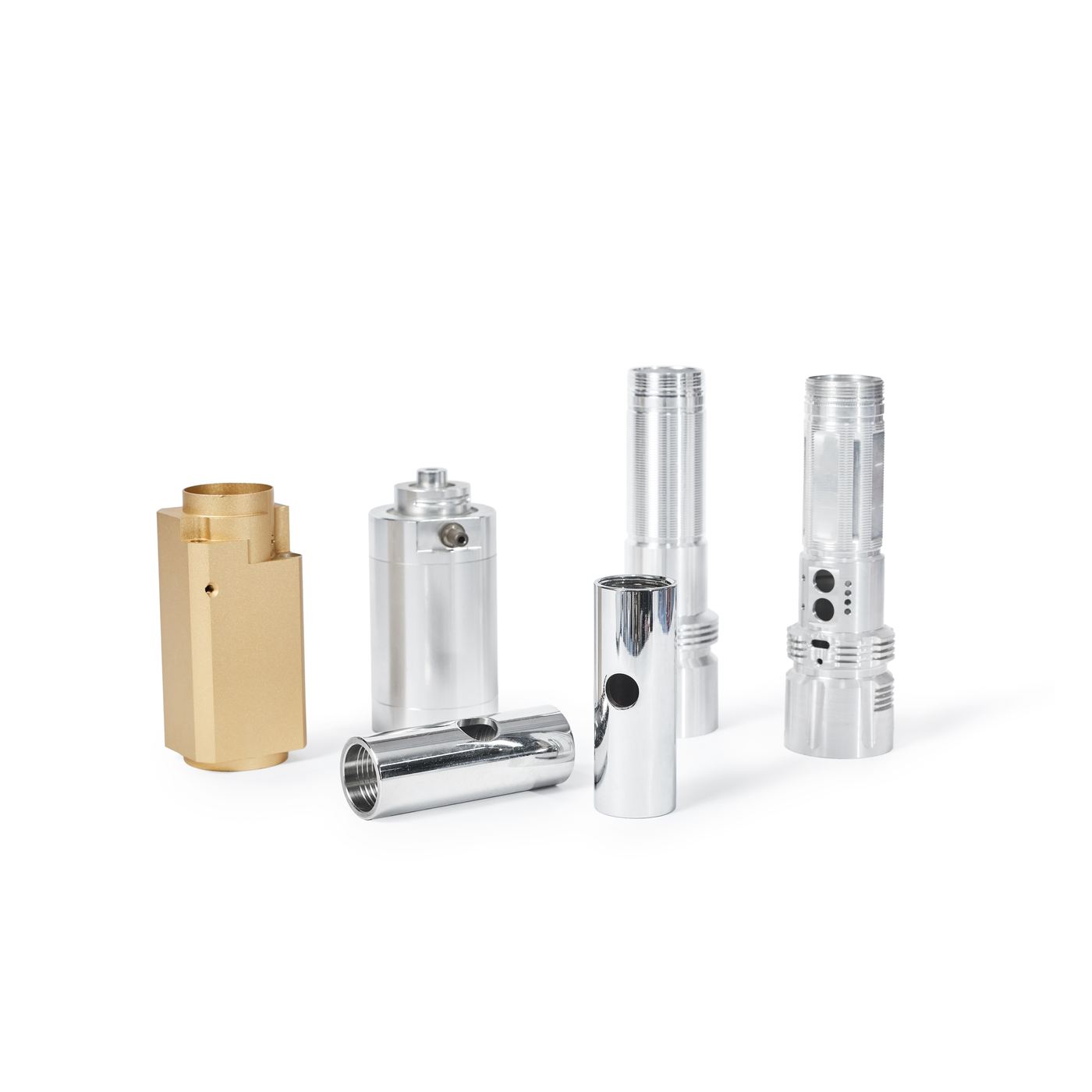
CNC turning and live tooling for shafts, pins, bushings, sleeves, threaded components and cylindrical housings. Concentric diameters, shoulders, grooves, bores and thread forms cut from bar or blank stock. Turned in Dongguan, China, to tolerances confirmed against your drawing.
In turning, the stock is held in a chuck or collet, or between centres, and the spindle rotates it. A fixed tool feeds along the axis and across it, so every surface it generates is concentric to the axis of rotation. That is the defining characteristic of the process, and the reason it suits cylindrical geometry: a turned diameter is round because the part was spinning, not because the tool path traced a circle.
On a conventional CNC lathe the tooling sits in a fixed position and the machine moves the tool or turret to it. That covers most turned work: external and internal diameters, shoulders and steps, grooves and reliefs, face features, bores, and external and internal threads. Single-point threading and grooving are done this way, because the form is generated by the relationship between the rotating part and the moving tool.
Live tooling adds driven tools to the lathe, so a drill or end mill can cut off-axis features while the part is still in the machine: cross-holes, flats, slots, keyways, or axial holes on a bolt circle. On a part with both turned and prismatic features, that removes a second operation and, more importantly, removes the re-chucking error a second operation would introduce.
Where a part needs features that only milling can reach efficiently, we run it as a milled operation rather than forcing it onto the lathe. When those features sit on several faces of the same part, the work goes to a 5-axis machine so the part is finished in one setup rather than a sequence of them. Which route we take depends on your drawing, not on which machine happens to be free.
| Process | CNC turning, with live tooling |
| Tightest tolerance | ±0.003mm (CNC) / ±0.001mm (grinding), when technically appropriate |
| Typical turned features | Concentric diameters, shoulders, grooves, bores, external and internal threads |
| Certifications | Certificate documentation available on request. |
| Part envelope | Confirmed per RFQ, send your dimensions and we confirm fit |
| Typical lead time | Confirmed with your quote |
| Materials | A broad range of metals and engineering plastics, see Materials & Finishes |
| Swiss-type work | Separate specification, see Swiss Machining |
And when milling or Swiss-type machining is the better answer. Turning is one process here, not the answer to every drawing.
Most real parts are a mix. A turned body with cross-holes and a flat can often be finished on the lathe with live tooling; a part with deep pockets on several faces usually belongs on a mill. See CNC milling for that side of the decision.
Turning is not always the right process. A part that is small in diameter and long relative to that diameter deflects in a chuck, so Swiss-type machining is usually the better route, compared below. Hardened surfaces and tight thread forms are often finished by precision grinding. And sharp internal corners that a rotating cutter cannot produce are better cut by EDM. If another process serves your drawing better, we will say so before you commit to a quote.
They are both turning. They are not the same process, and they do not hold the same parts.
The part is held in a chuck or collet, or between centres, and rotated while the tool travels to it. Material beyond the workholding is unsupported, so the further the part sticks out and the thinner it is, the more it deflects under cutting force. Suited to a wide range of diameters, and to parts whose features sit on the outside diameter, the bore and the face.
The bar stock feeds axially through a guide bushing and the tool cuts immediately at the bushing, so the material is supported right at the point of cut instead of hanging in free space. That is what makes very slender, high length-to-diameter parts practical, and why the process is associated with small precision components rather than with larger turned work.
| Part is short and stiff | Conventional turning |
| Part is small in diameter and long | Swiss-type |
| Features sit on the OD, bore and face | Conventional turning |
| Tolerance is lost to deflection | Swiss-type |
If your part is small in diameter and long relative to that diameter, Swiss-type is likely the better process and it is the one to quote. Swiss-type machining carries its own published specification, ±0.01 mm on turned features, documented on the Swiss lathe machining page. That figure belongs to the Swiss process and is not the figure that applies to conventional turning, which is quoted to the tolerances on your drawing.
A capability figure is not a default. It is the result of a specific part, material and setup.
We work to ±0.003mm on turned features when the geometry, material and setup allow, and ±0.001mm on suitable ground features. Those figures are the ceiling of what the process can hold on the right part, not a number that applies to every dimension on every drawing. On a turned part, tolerance is rarely one number anyway: a diameter carries a size, a roundness and a position relative to the datums, and it is usually the last two that decide whether the part assembles.
Four things move a turned feature away from that figure:
Send the drawing with critical diameters, threads and datums marked, plus any runout or concentricity requirement between features. Medical screws, pins and instrument shafts that need a documented quality route run through our ISO 13485 medical machining scope. Our engineers confirm which tolerances are achievable on which features, and tell you where a looser callout would cut cost without affecting function.
| Overhang | Length unsupported outside the chuck or collet |
| Wall thickness | Thin sleeves and bushings deflect under clamping and cutting force |
| Interrupted cuts | Cross-holes, keyways and flats break the cut |
| Material | Machinability and thermal movement |
| Measurement | A diameter that cannot be measured repeatably cannot be controlled |
Tolerances vary by geometry, feature size, material, setup and inspection requirements. Critical dimensions are confirmed during engineering review, against your drawing.
On a turned part the relationship between features usually matters more than any single dimension.
A turned diameter is not just a size. It is a size, a roundness and a position relative to the datums, and it is often the last of those that decides whether a shaft fits its bearing or a sleeve fits its housing. Runout between two diameters, concentricity between a bore and an outside diameter, and the squareness of a shoulder to the axis are all checked as relationships rather than as isolated sizes.
Threads get their own attention. Pitch diameter, thread form and the position of the thread relative to the shoulder are what determine whether a mating component screws on cleanly, and a thread that gauges correctly on its own can still bind once the mating part is fitted. Where a drawing is ambiguous about which feature controls the datum, we raise it during engineering review rather than assume one and find out at final inspection. That is the point at which a change is still cheap.
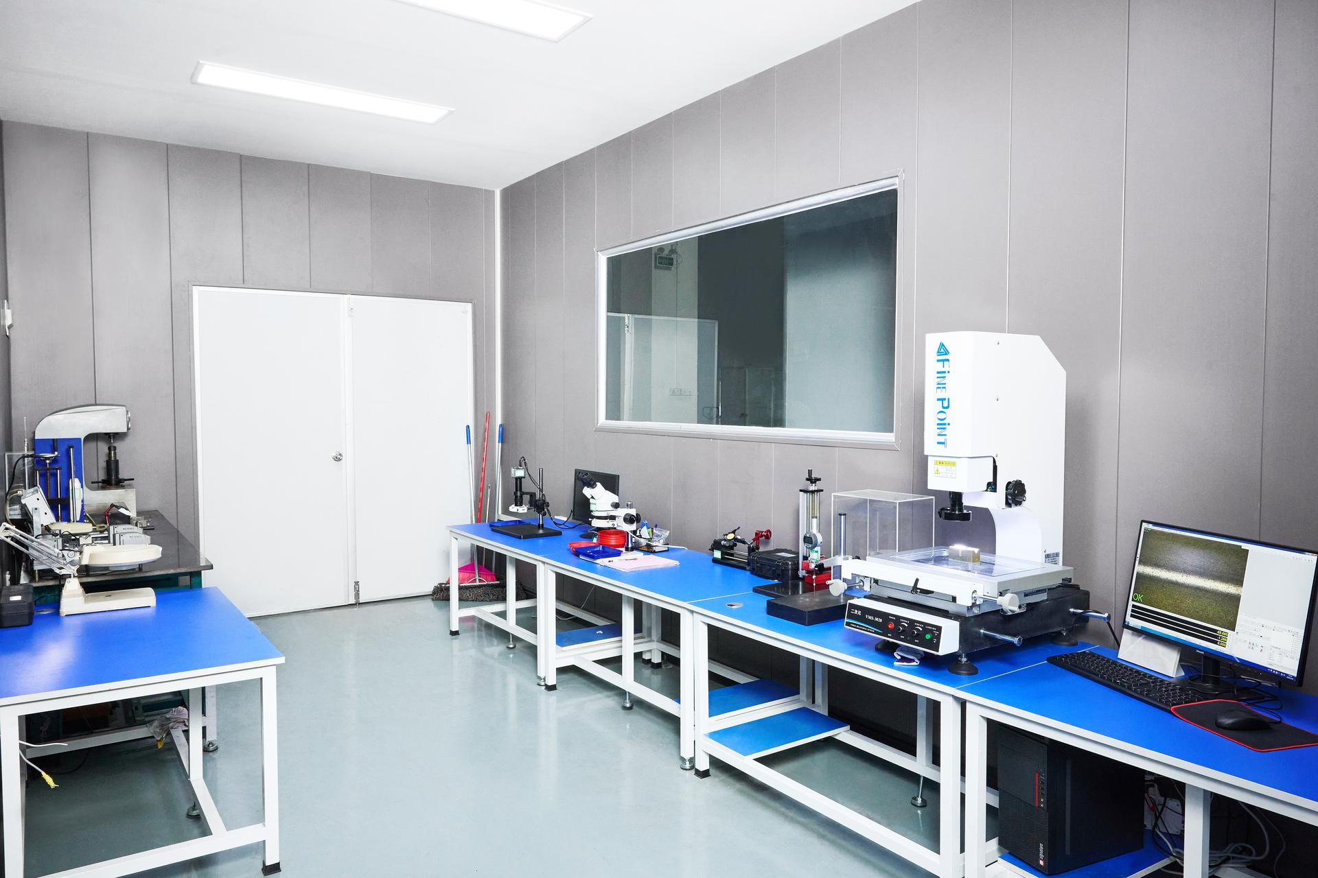
Inspection runs through four stages on every order: incoming material check, with material certification verified against your spec before it reaches the machine; in-process inspection, with operators checking dimensions against your print at set intervals through the run; final inspection, first article and final inspection against your drawing before parts ship; and reporting, with dimensional reports and traceability documentation shipped alongside the parts. Details on our Quality & Certifications page.
| Incoming | Material certification checked against your spec |
| In-process | Dimensional checks at set intervals through the run |
| Final | First article and final inspection against your drawing |
| Reporting | Dimensional reports and traceability documentation |
A staged 25-piece shaft program where radial runout and thread form were the critical characteristics. The documented route combined precision machining, laser hardening to 52 ± 2 HRC on the thread-grinding surface, and thread grinding. The batch was released after a go/no-go thread gauge check recorded in our own inspection documentation, with a 3D dimensional report and material documentation supplied. It is a useful read on how runout, a hardened thread surface and a fit concern were handled.
Read the Mediso case study →CNC turning suits parts with rotational symmetry: shafts, pins, studs, bushings, sleeves, spacers, adapters, threaded components, cylindrical housings and valve or nozzle bodies. Turned connector contacts, pogo pin barrels and terminals are a regular part of that work — see connector and pogo pin components. Typical turned features are concentric diameters, steps and shoulders, grooves and reliefs, external and internal threads, bores, counterbores and face features. If the part is prismatic rather than round, or its main features are pockets and slots on flat faces, CNC milling is usually the better route.
In turning, the workpiece rotates and a fixed tool feeds along and across it, so every cut is concentric to the axis of rotation. In milling, the workpiece is held still and a rotating multi-tooth cutter moves around it, so the geometry comes from the tool path rather than from the part's rotation. Turning is the natural fit for cylindrical and threaded geometry. Milling is the natural fit for flat, pocketed and multi-sided geometry. The two are often combined on the same part, and live tooling on a lathe covers cross-holes, flats and slots without a second setup.
Conventional turning holds the part in a chuck or collet and the material sticks out unsupported, so the longer and thinner the part, the more it deflects under cutting force. Swiss-type machining feeds the bar through a guide bushing that supports the material right at the cutting point, which is what makes very slender, high length-to-diameter parts practical. If your part is small in diameter and long relative to that diameter, Swiss-type is likely the better process. Swiss-type machining has its own specification, documented on our Swiss machining page.
A broad range of metals and engineering plastics, including aluminum, steel, stainless steel, titanium, brass, copper, and plastics such as Delrin, Nylon, PEEK and PTFE. Material affects tooling, cutting strategy, chip control and lead time, so the grade is confirmed against your drawing. The full list is on our Materials & Finishes page.
We work to ±0.003mm on turned features when the geometry, material and setup allow, and ±0.001mm on suitable ground features. What a turned feature can actually hold depends on more than the machine: how far the part sticks out of the chuck unsupported, wall thickness on thin-walled sleeves and bushings, whether there are interrupted cuts such as cross-holes, the material, and how the feature will be measured. Critical dimensions are confirmed against your drawing during engineering review.
Yes. There is no MOQ, and a single turned prototype and a production run go through the same engineering review and the same inspection process. DFM notes, tolerance questions and fixturing or tooling constraints raised at the prototype stage are carried into the production quote, so the part does not have to be re-engineered later.
A 3D model or 2D drawing (STEP, IGES, SLDPRT, DXF or PDF), the material and grade, the quantity, and any critical tolerances, datums or finishes marked on the print. For turned parts, mark the diameters and threads that matter, plus any runout or concentricity requirement between them. Include a target date if you have one. We read the drawing before pricing it and flag anything that affects cost or lead time.
Upload your CAD file (STEP, IGES, SLDPRT or DXF), material, quantity and deadline. Our engineering team reviews manufacturability and comes back with a quote. No automated pricing tool, no shared sales inbox.